

In this project we had to create a circuit that would count to 80 and then stop at 80. we also had to make it able to, at the flip of the switch reset the counter to zero, and have another switch that pauses it.
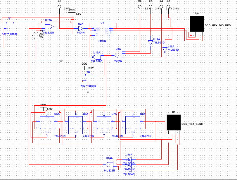
Multisim circuit
PLD Circuit

The main difference between design mode and PLD is the ability of the PLD mod to upload it to a programmable chip. Also PLD mode offers the ability to make inputs and outputs, which have numbers corresponding to the certain pins on the chip. In addition, design mode can not be uploaded meaning yoou would have to wire it by yourself on a breadboard, which could result in wiring mistakes.
Bill of materials
Conclusion
The difference between the SSI and MSI circuits is just the amount of gates, SSI has <10 gates whereas MSI has 10-100 gates. one of the limitations of the circuit that I created was that it lacked the ability to go back a number in the situation that an operator accidentally hit the button. The ripple effect occurs in asynchronous counters where the next gate has to wait for the signal of the clock to come through the gate before it. this waiting is known as the ripple affect as the clock signal ripples through the gates in the counter. There were some people who instead of using a 4 input hex display, used a demultiplexer to change the 4 inputs into 7 in order to use a 7 input display.
